Enter an error code to view the result
Matching entries appear here immediately, including the product series, a short description, the cause and the recommended remedy where available.
Technical article
Technical guide to the Lenze 8200 vector, including key data, model overview, error codes, diagnostic guidance and replacement information.
The search field is the fastest route to the relevant Lenze error code. Enter a code to see its meaning, series and diagnostic guidance directly on this page. The tables below provide a representative excerpt.
Matching entries appear here immediately, including the product series, a short description, the cause and the recommended remedy where available.
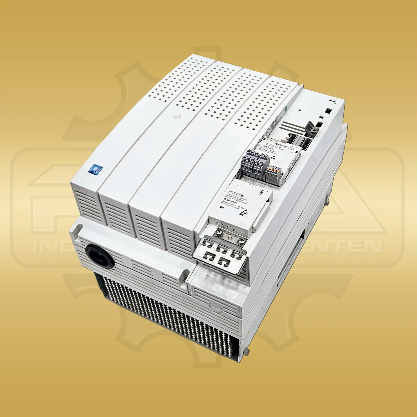
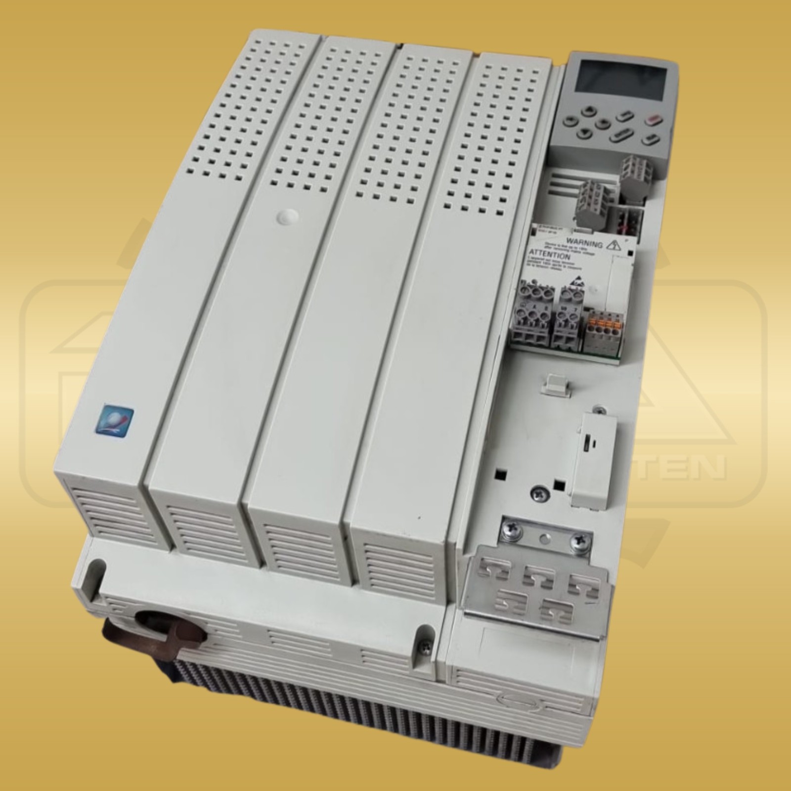
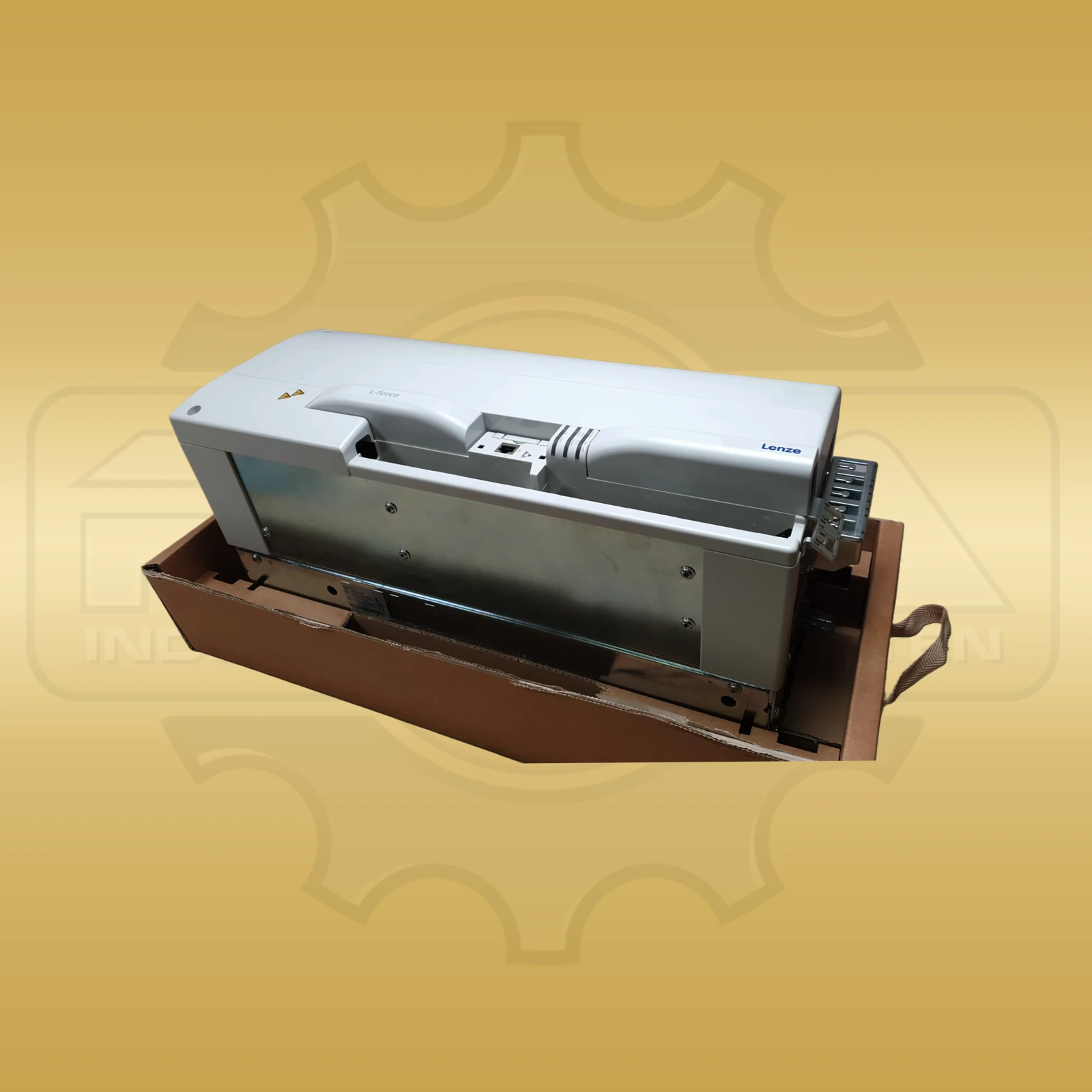
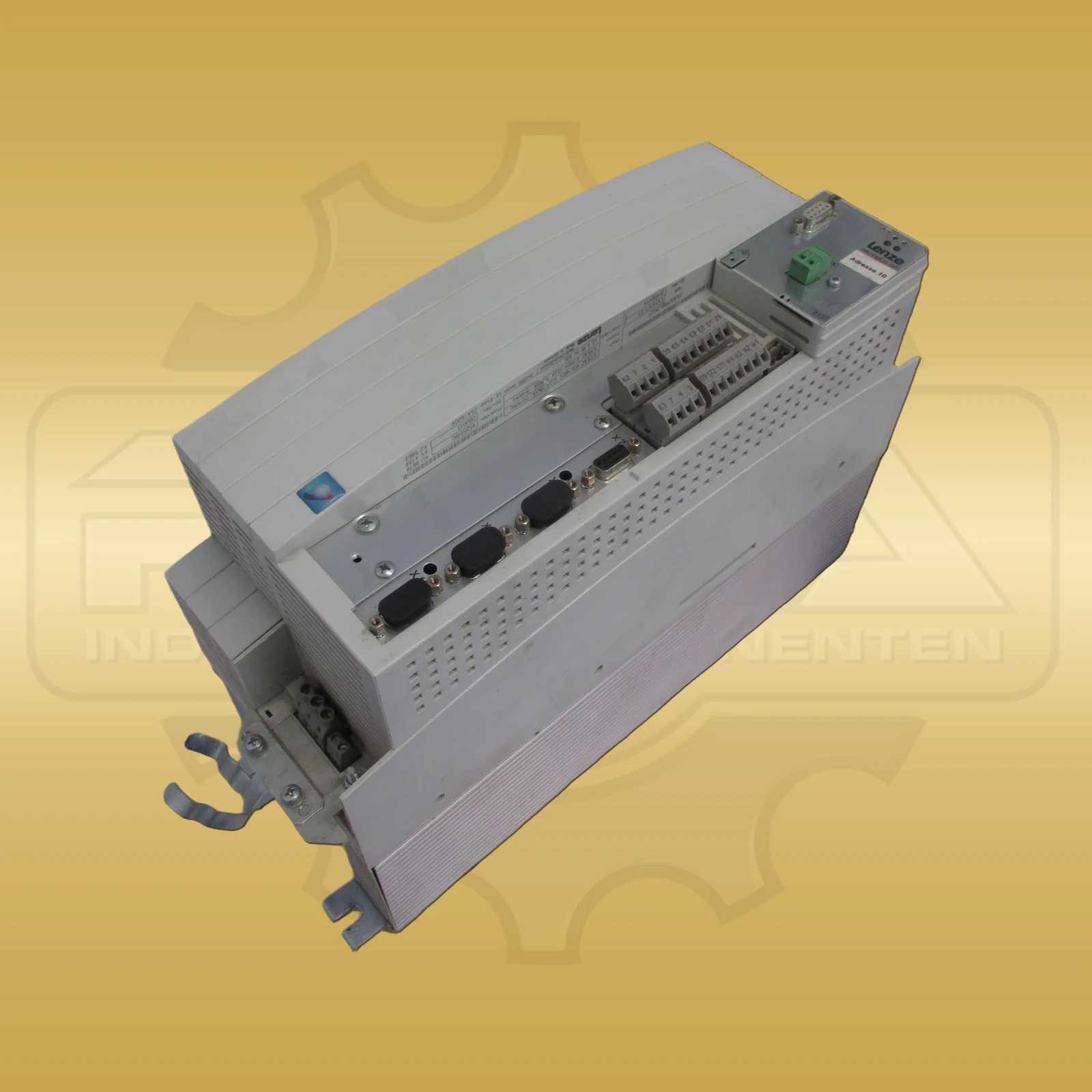
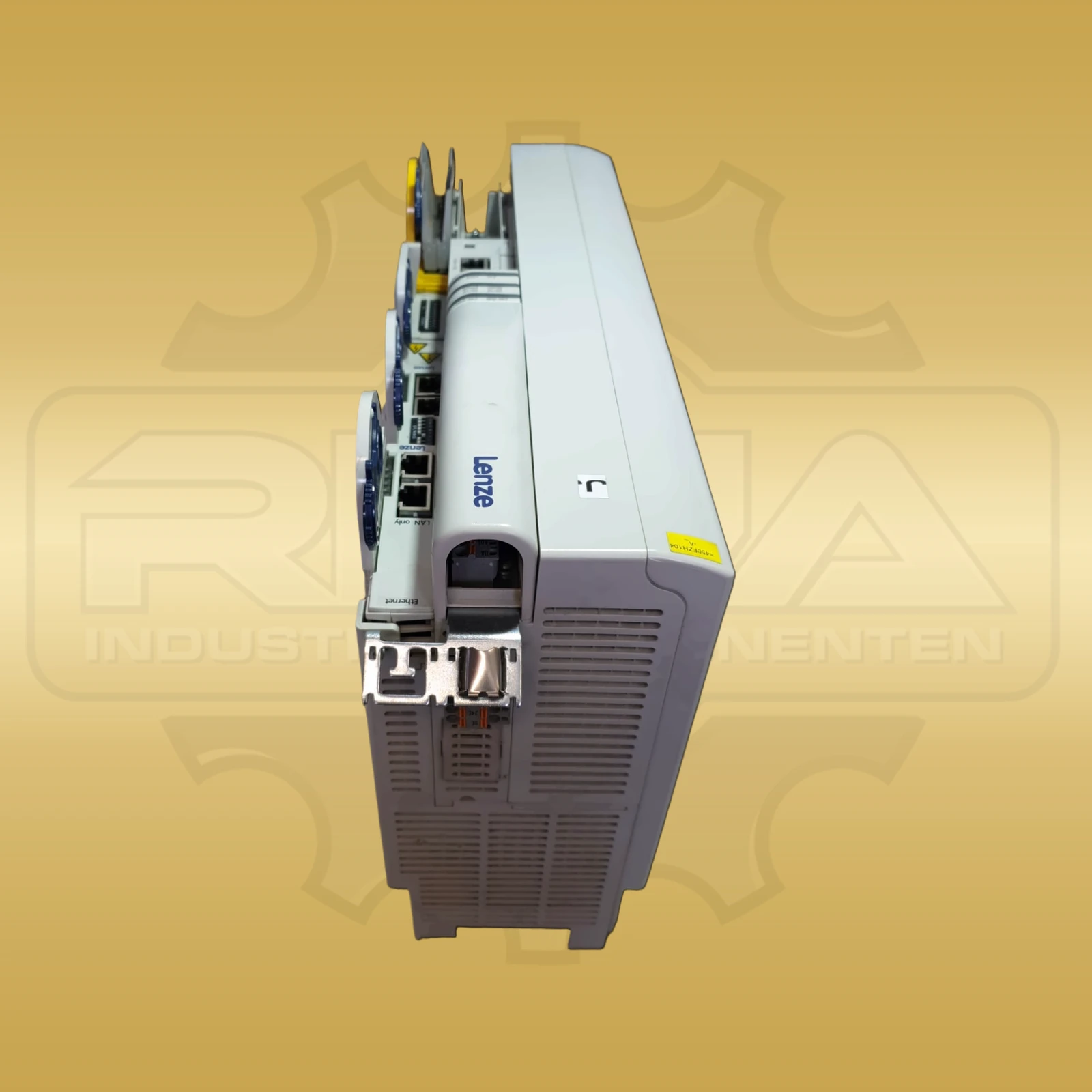
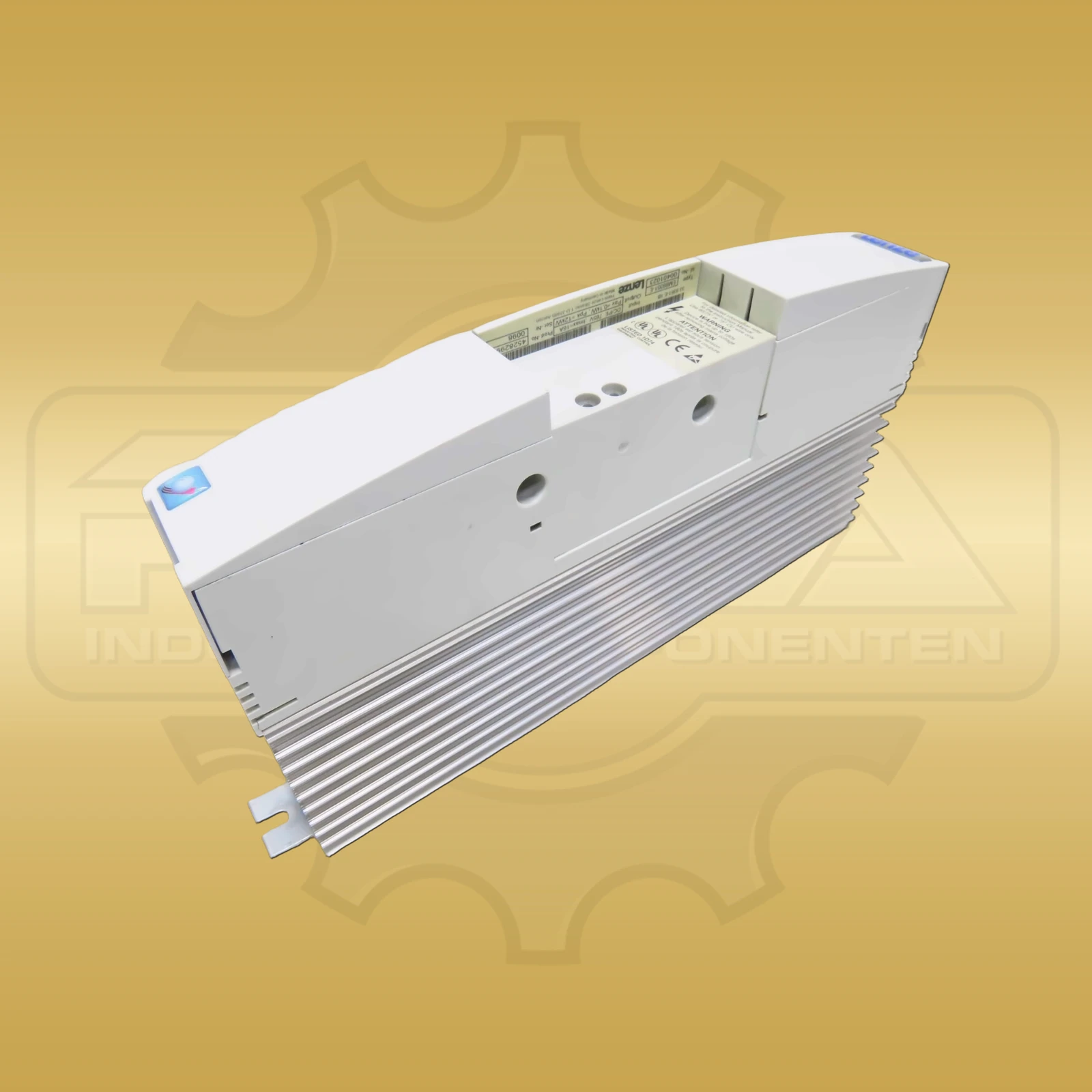
The Lenze 8200 vector is the most widely used frequency converter from Lenze and, with millions of installed devices, is one of the best-known standard drives in conveyor, packaging and production technology worldwide.
This page is aimed at service technicians and maintenance personnel who diagnose a 8200 vector, assign a suitable replacement device or need technical information quickly at hand.
The error-code search above is the main feature of this page. It displays the relevant information directly in each result without requiring additional subpages.
The tables further down show typical and frequently searched messages for technical orientation. Use the search field above to query the complete dataset.
The Lenze 8200 vector is one of the best-known frequency converters in the industrial fleet and has been used in numerous conveyor systems, packaging machines and production lines. This is exactly why the series is still particularly relevant in everyday service today.
Three points are particularly important for troubleshooting with the 8200 vector: the reliable identification of the correct size, checking the control terminals and the correct classification of the display messages in the LED-Keypad. Many faults can be isolated at an early stage if the mains supply, controller enable, parameter set and motor connection are systematically checked.
If you are looking for Lenze 8200 vector error codes, Lenze 8200 vector technical data or Lenze 8200 vector terminal assignment, you will find the most important information here in a compact technical form.
For the first classification, the 8200 vector primarily requires the power range, voltage range, control method, protection type and expandability via option modules. This data helps to correctly assign device type and application.
| Parameters | Value |
|---|---|
| Performance range | 0,25–90 kW |
| Rated voltage | 3 × 380–480 V AC ±10 %, 50/60 Hz |
| Protection class | IP20 (standard), IP54 with mudguard |
| Rules procedure | U/f characteristic, vector control with or without encoder, servo mode |
| Ambient temperature | 0–40 °C (up to 55 °C with derating) |
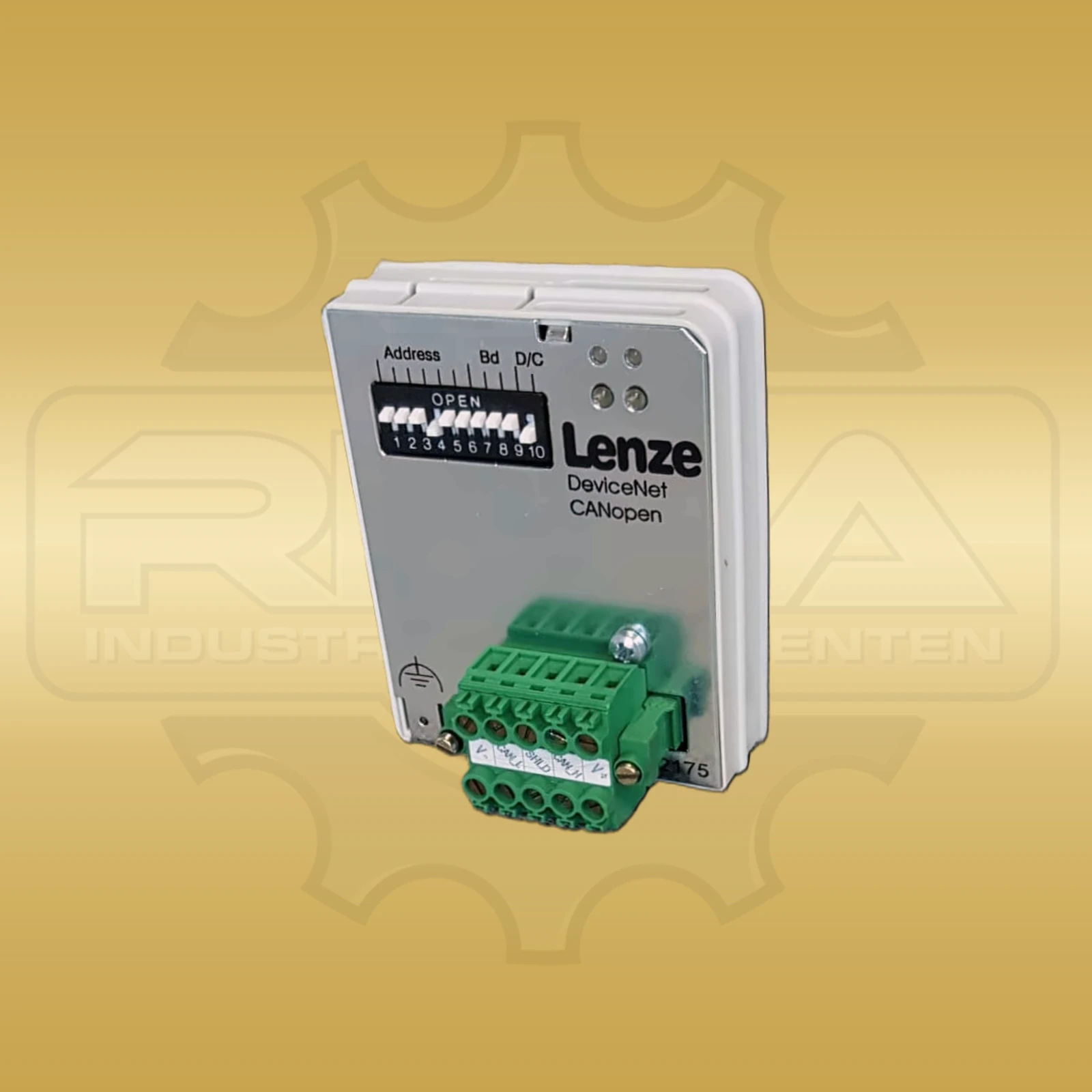
| Communication | AS-Interface, PROFIBUS, CANopen, DeviceNet via option modules |
| Option modules | E82Z-Steckmodule for fieldbus, additional I/O and encoder |
The order number of the 8200 vector follows the pattern E82EV + power code + voltage code + housing identifier. In practice, this structure is important if a replacement device is to be assigned using nameplate data, parts lists or existing documentation.
The following overview refers to 3 x 400 V devices for control cabinet installation with the suffix K4C.
| Order number | Rated power |
|---|---|
| E82EV371K4C | 0,37 kW |
| E82EV551K4C | 0,55 kW |
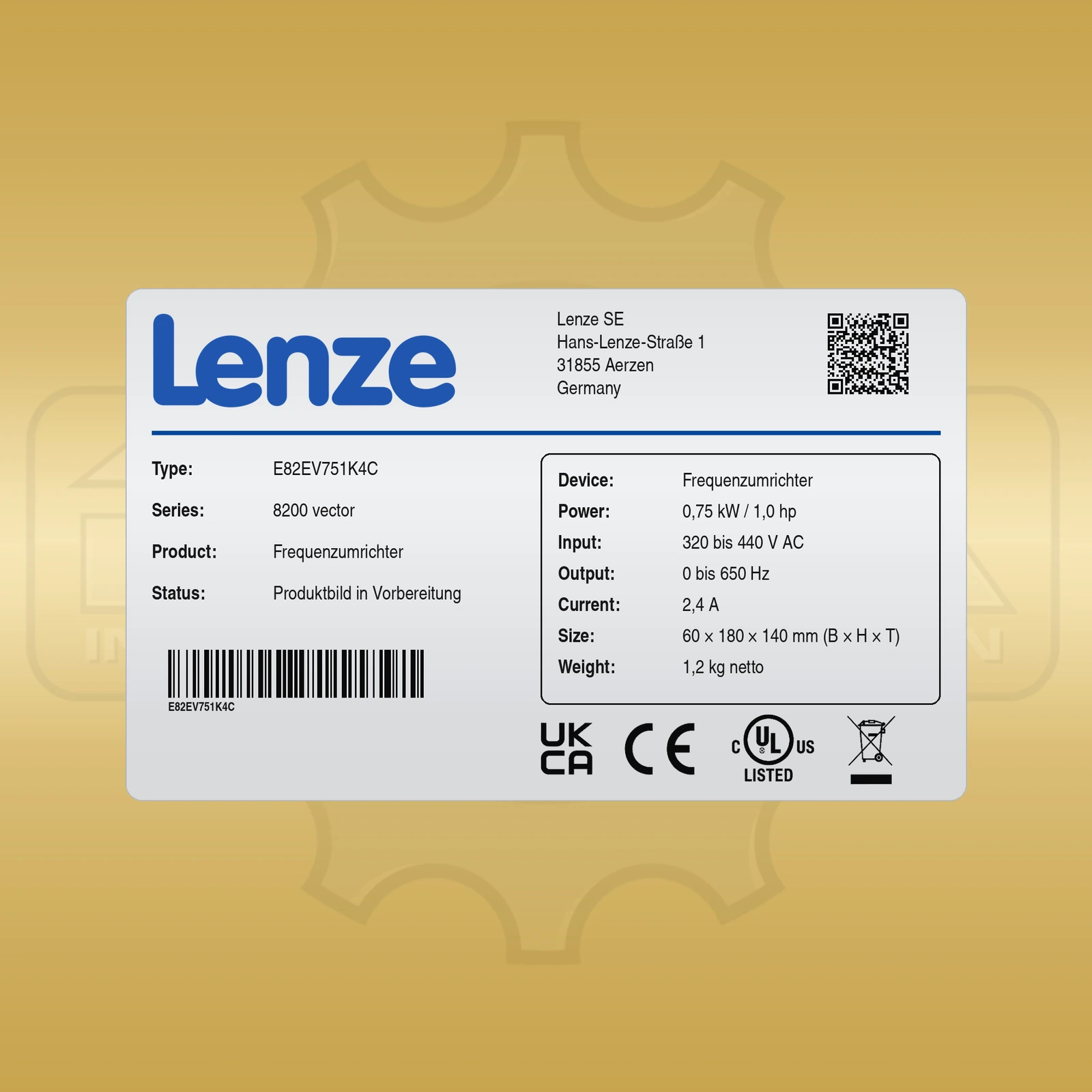
| E82EV751K4C | 0,75 kW |
| E82EV152K4C | 1,5 kW |
| E82EV222K4C | 2,2 kW |
| E82EV302K4C | 3,0 kW |
| E82EV402K4C | 4,0 kW |
| E82EV552K4C | 5,5 kW |
| E82EV752K4C | 7,5 kW |
| E82EV113K4C | 11 kW |
| E82EV153K4C | 15 kW |
| E82EV223K4C | 22 kW |
| E82EV303K4C | 30 kW |
| E82EV453K4C | 45 kW |
| E82EV903K4C | 90 kW |
When servicing is required, the X5 terminal strip is one of the most important test areas. Controller enable, analog inputs, digital inputs and fault relays are often more relevant in the initial diagnosis than the power unit itself.
| Clamp | Designation | Function/Note |
|---|---|---|
| 1 | GND | Reference potential for analog signals |
| 2 | +10 V Reference | Reference voltage, max. 10 mA – for potentiometer setpoint generator |
| 3 | E1 - analog input 1 | Setpoint, 0…+10 V or 4…20 mA, switchable via DIP-Switch |
| 4 | E2 - analog input 2 | Additional setpoint, 0…+10 V or 4…20 mA |
| 5 | GND | reference potential |
| 6 | A1 - analogue output 1 | Actual value, e.g. B. Output frequency, 0…+10 V |
| 7 | A2 - analogue output 2 | Actual value, e.g. B. Motor current, 0…+10 V |
| 28 | Controller enable RF | HIGH = 24 V = released, LOW = blocked. Pulse blocking if release is missing. |
| E1–E4 | Digital inputs | 24-V-Pegel, freely parameterizable, e.g. E.g. fixed frequencies, jog mode, direction of rotation, reset |
| A1 | Digital output | Open collector, parameterizable, e.g. B. ready for operation or frequency reached |
| K1 / K1C / K1A | Fault relay | Changeover contact – opens in the event of a fault, fail-safe principle |
The following table lists the documented error messages of the 8200 vector. The display appears in the 3-stelligen LED- display of the keypad. Trip-type messages require manual acknowledgment, while warnings can disappear automatically after the cause has been eliminated.
| Code | Description | Cause | Remedy |
|---|---|---|---|
| noer | No disturbance | - | - |
| ccr | System malfunction | Strong interference on control lines; Ground or ground loops in the wiring | Lay control cables shielded |
| ce0 | Communication error on AIF | Transmission of control commands via AIF is disrupted | Insert the communication module firmly into the handheld terminal |
| ce1 | Communication error on CAN-IN1 during sync control | CAN-IN1 receives incorrect data or communication is interrupted | Check plug connection bus module/FIF; check channels; If necessary, increase monitoring time |
| ce2 | Communication error on CAN-IN2 | CAN-IN2 receives incorrect data or communication is interrupted | Check plug connection bus module/FIF; check channels; If necessary, increase monitoring time |
| ce3 | Communication error on CAN-IN1 during event/time control | CAN-IN1 receives incorrect data or communication is interrupted | Check plug connection bus module/FIF; check channels; If necessary, increase monitoring time |
| ce4 | BUS-OFF | Too many incorrect telegrams on the system bus | Check bus termination; Check shield connection; PE-Check connection; check bus load; If necessary, reduce the baud rate |
| ce5 | CAN Time out | System bus wiring or system bus configuration incorrect | Check wiring and system bus configuration |
| ce6 | Function module system bus warning or BUS-OFF | Internal error; CAN-Controller reports warning or BUS-OFF | Check device status and fieldbus environment |
| ce7 | Communication error during remote parameterization via system bus | Participant does not respond or is not present | Check bus termination, shield connection, PE-connection and bus load |
| EEr | External fault TRIP-SET | A digital signal assigned TRIP-Set is activated | Check external encoder or signal source |
| ErP0–ErP19 | Communication interruption between keypad and basic device | Various causes | Check connection and device |
| FAn1 | Fan malfunction | Fan defective or not connected | replace or connect fans; Check wiring |
| H05 | Internal disturbance | Internal error | Check device |
| id1 | Incorrect parameter identification | Motor not connected | Connect motor |
| LP1 | Motor phase error | Failure of one or more motor phases; Motor current too low | Check motor cables; Check Umin increase; Adjust engine power or C0599 |
| LU | DC link undervoltage | Mains voltage or DC-composite voltage too low | Check mains voltage and supply module; Use correct mains voltage |
| OC1 | Short circuit | Short circuit in motor cable or winding; brake resistor defective; Motor cable charging current too high | Find the cause of the short circuit; Check motor cable and brake resistor; Use shorter or lower capacity motor cable |
| OC2 | Ground fault | One motor phase is in contact with ground; Capacitive charging current of the motor cable too high | Check motor and motor cable; Use a shorter or lower capacity cable |
| OC3 | Drive controller overload during startup or short circuit | Startup time set too short; defective motor cable; Short circuit in the motor | extend ramp-up time; Check drive design; Check wiring and motor |
| OC4 | Drive controller overload in process | Expiry time set too short | extend expiration time; Check the design of the external braking resistor |
| OC5 | Drive controller overload in stationary operation | Frequent and too long overloads | Check drive design |
| OC6 | Motor overload I² x t | Motor thermally overloaded | Check drive design; Check setting of C0120 |
| OH | Heat sink temperature > +85 °C | Ambient temperature too high | Allow the drive controller to cool down and ensure better ventilation |
| OH | Heat sink temperature > +80 °C Warning | Heat sink heavily dirty or impermissibly high currents | clean heat sink; Check drive design and load |
| OH3 | PTC-Ümonitoring TRIP | Motor too warm or no PTC connected | Check drive design; Connect PTC or switch off monitoring |
| OH4 | Drive controller overtemperature | Interior of the drive controller too warm | reduce burden; improve cooling; check fan; Check drive design |
| OH51 | PTC-Ümonitoring | Motor too warm or no PTC connected | Check drive design; Connect PTC or switch off monitoring |
| OU | DC link overvoltage | Mains voltage too high; braking operation; creeping ground fault on the motor side | Check supply voltage; extend expiration times; Check braking resistor; Check motor and cable for ground fault |
| OUE | External DC link overvoltage | Creeping ground fault on the motor side | Check motor supply cable and motor for ground fault |
| Pr | Parameter transmission with the keypad incorrect | All parameter sets are defective | Repeat data transfer or load Lenze setting |
| Pr1 | PAR1 transferred incorrectly | Parameter set 1 is defective | Repeat data transfer or load Lenze setting |
| Pr2 | PAR2 transferred incorrectly | Parameter set 2 is defective | Repeat data transfer or load Lenze setting |
| Pr3 | PAR3 transferred incorrectly | Parameter set 3 is defective | Repeat data transfer or load Lenze setting |
| Pr4 | PAR4 transferred incorrectly | Parameter set 4 is defective | Repeat data transfer or load Lenze setting |
| Pr5 | Internal error EEPROM | EEPROM defective | Check device |
| Pt5 | Time error during parameter set transfer | Data flow from keypad or PC interrupted | Repeat data transfer or load Lenze setting |
| rSt | Auto-TRIP-Reset error | More than 8 error messages in 10 minutes | Depending on the underlying error message |
| sd5 | Wire break analog input 1 | Current at the analog input is less than 4 mA with setpoint range 4…20 mA | Close the circuit at the analog input |
| sd7 | Wire break analog input 2 | Current at the analog input is less than 4 mA with setpoint range 4…20 mA | Close the circuit at the analog input |
Typical wear parts on the 8200 vector are fans, especially from 3 kW upwards, intermediate circuit capacitors with age-related loss of capacity and, in the case of recurring Pr errors, also EEPROM--related assemblies. Especially with older devices, a distinction should always be made between peripheral errors, parameter issues and real device malfunctions.
Before replacing, the existing parameter set should definitely be saved via the keypad. This shortens the restart and makes it easier to adopt system-specific settings.
Shop & Inquiry
After the technical classification, the direct route to the right replacement device, compatible spare parts or a specific product inquiry is usually the most sensible next step.
If you are looking for error codes for another Lenze series, you will also find additional technology pages for Lenze 8400 motec and Lenze EVS9300. This allows you to narrow down the right series more quickly.
In practice, undervoltage and overvoltage messages such as LU and OU, overcurrent errors OC1 to OC6, temperature messages OH and OH3 as well as parameter errors such as Pr or Pt5 occur particularly frequently.
The 8200 vector is particularly common in conveyor systems, packaging machines and general production technology. Because of its large installation base, it is still often found in existing systems today.
Controller enable, analog inputs, digital inputs and the fault relay on X5 are particularly relevant. Many causes of errors are not in the power section, but rather in enables, setpoints or external control signals.
Before replacing, the parameter set should always be copied or saved using the keypad. This means system-specific settings can be transferred to a replacement device more quickly.
The information on this page has been compiled with the greatest care and is based on many years of practical experience with Lenze frequency converters. However, they do not replace the official Lenze documentation and serve exclusively as a guide for qualified specialist personnel.
Work on frequency converters may only be carried out by qualified electricians in accordance with DIN VDE 0105-100. Danger to life due to residual voltage in the DC link: After switching off, wait at least 10 minutes or adhere to the waiting time specified by the manufacturer.
REHA-Industrial components assumes no liability for damages resulting from the use of this information. Lenze is a registered trademark of Lenze SE.