Enter an error code to view the result
Matching entries appear here immediately, including the product series, a short description, the cause and the recommended remedy where available.
Technical article
Technical guide to the Lenze EVS9300 series, including key data, connections, typical error codes, diagnostic steps and sourcing information.
The search field is the fastest route to the relevant Lenze error code. Enter a code to see its meaning, series and diagnostic guidance directly on this page. The tables below provide a representative excerpt.
Matching entries appear here immediately, including the product series, a short description, the cause and the recommended remedy where available.
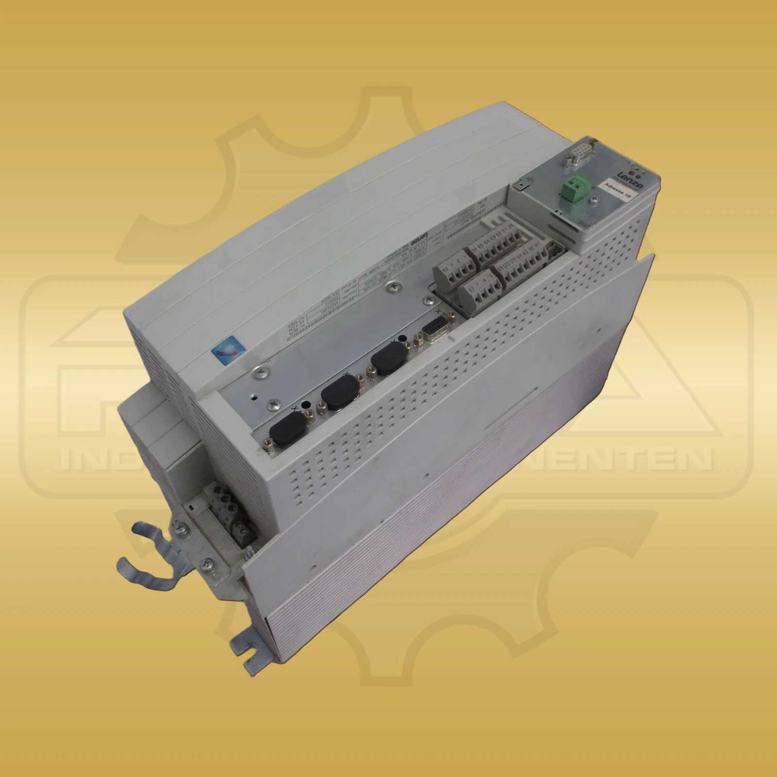
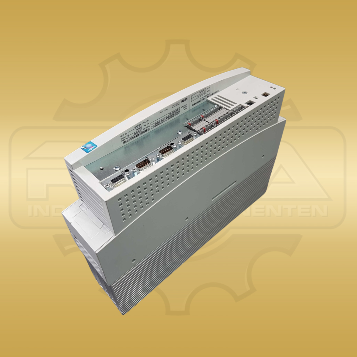
The Lenze EVS9300 series is one of the classic servo inverters for dynamic drive tasks in mechanical engineering, packaging technology, handling axes and positioning applications.
This page helps you quickly classify model size, terminal assignment, typical error codes and initial diagnostic measures so that the replacement device or repair route can be clarified more quickly.
The error-code search above is the main feature of this page. It displays the relevant information directly in each result without requiring additional subpages.
The tables further down show typical and frequently searched messages for technical orientation. Use the search field above to query the complete dataset.
The EVS9300 series is one of the well-known Lenze servo inverters for demanding applications with precise speed and torque control. Three points in particular are crucial in everyday service: quickly assigning the correct model, checking the relevant control connections and reliably evaluating fault messages.
Especially with older existing systems, there is often only nameplate data, individual error messages or incomplete documents. This makes it all the more important to have a compact technical overview that allows you to quickly classify the size, typical causes of errors and the appropriate next steps.
Anyone looking for Lenze EVS9300 error codes, Lenze EVS9300 technical data or Lenze 9300 terminal assignment will find the most important information in a structured form here.
In practice, the initial classification requires network data, power range, interfaces, encoder evaluation and environmental conditions. This basic data helps to correctly assign devices and exclude obvious sources of error early on.
| Parameters | Value |
|---|---|
| Rated voltage | 3 × 400 V AC ±10 %, 50/60 Hz |
| Performance range | 0,37–75 kW |
| Rules procedure | Field-oriented control (FOC), vector and U/f operation |
| Protection class | IP20 |
| Ambient temperature | 0–45 °C (up to 55 °C with derating) |
| Storage temperature | −25 to +60 °C |
| Interfaces | LECOM A/B (RS232/RS485), CAN, optional PROFIBUS-DP / INTERBUS-S |
| Donor evaluation | Resolver, Sin/Cos 1 Vpp, incremental encoder (HTL/TTL) |
| Brake control | 24 V DC holding brake via integrated output |
Within the EVS9300 series, the devices differ primarily in terms of performance class and nominal current. This assignment is particularly important for exchange and procurement because in many cases there is initially only a rough performance specification or an incomplete type designation.
Where appropriate product pages are available, the individual models can be accessed directly from the table. This makes it easier to quickly get from the diagnosis to the appropriate replacement device.
| model | Rated power (S1) | Maximum power (S6) | Rated current approx. |
|---|---|---|---|
| EVS9321 | 0,37 kW | 0,55 kW | 1,2 A |
| EVS9322 | 0,75 kW | 1,1 kW | 2,4 A |
| EVS9323 | 1,5 kW | 2,2 kW | 4,1 A |
| EVS9324 | 3,0 kW | 4,0 kW | 7,6 A |
| EVS9325 | 5,5 kW | 7,5 kW | 13,5 A |
| EVS9326 | 11 kW | 15 kW | 25 A |
| EVS9327 | 18,5 kW | 22 kW | 39 A |
| EVS9328 | 30 kW | 37 kW | 62 A |
| EVS9329 | 45 kW | 55 kW | 90 A |
| EVS9330 | 75 kW | 75 kW | 150 A |
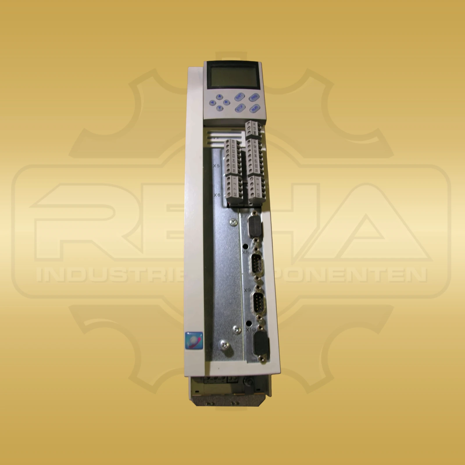
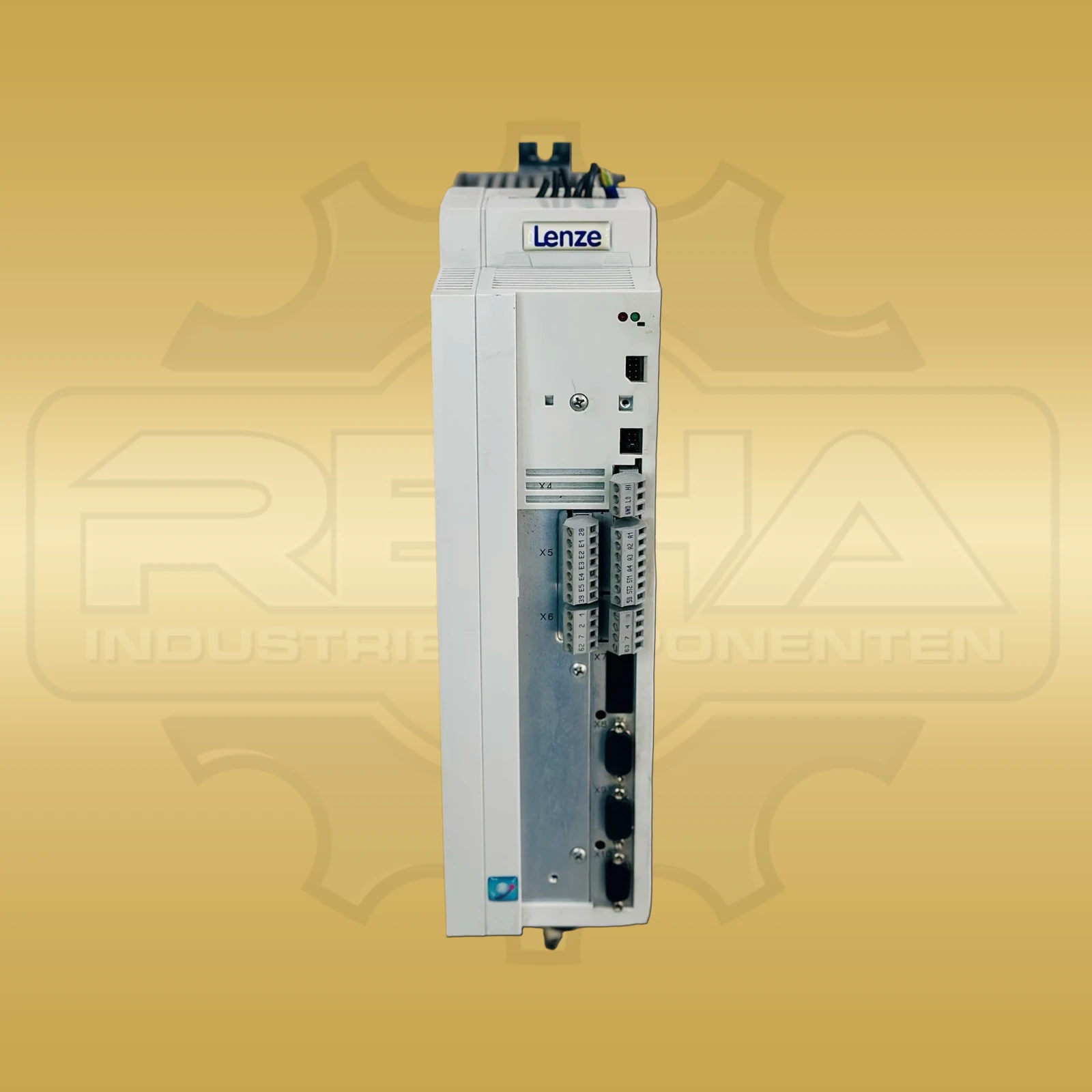
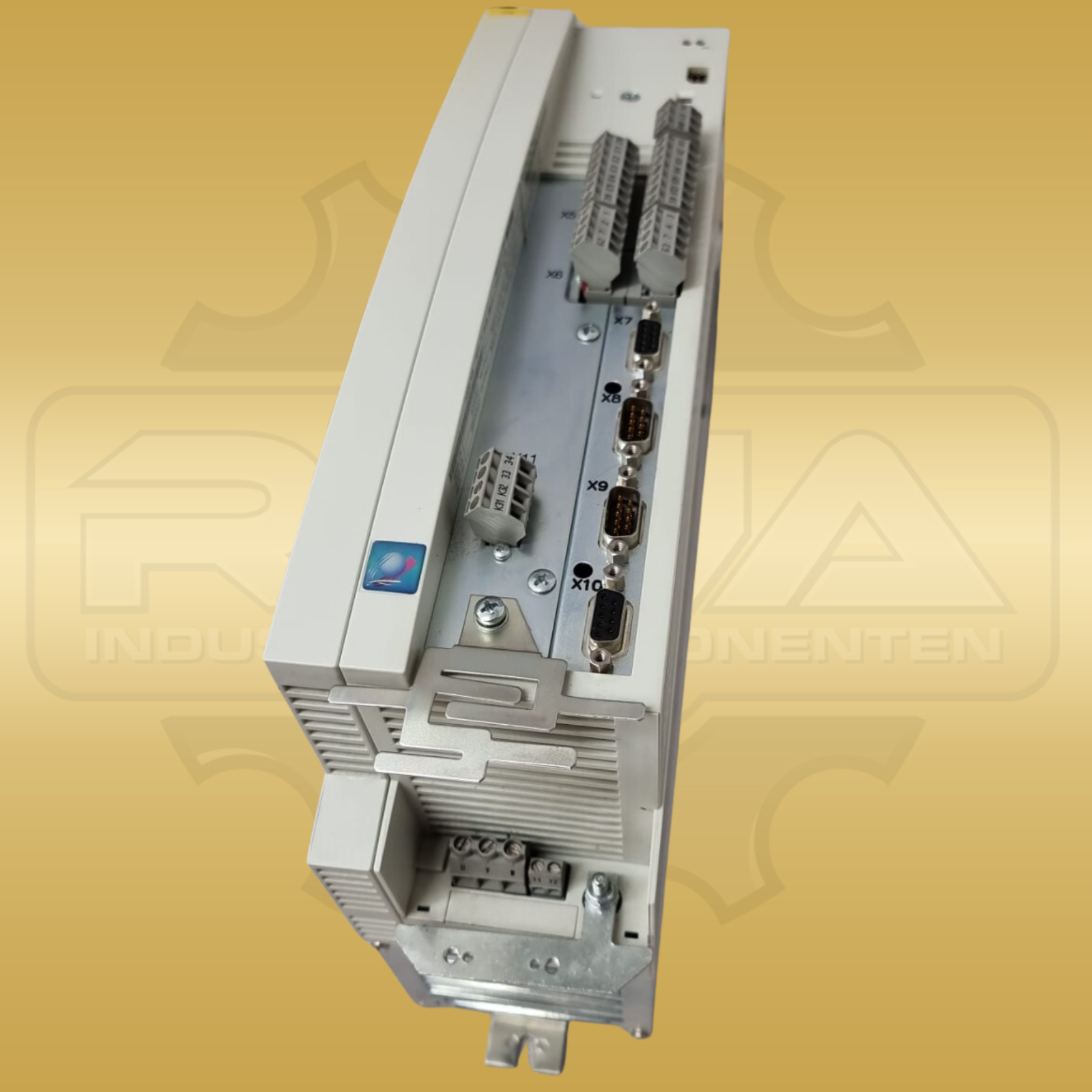
When servicing is required, the terminal level is particularly relevant because many faults are not in the power section, but in releases, setpoint signals or external control circuits. In particular, the controller release and the clean separation of analog and digital reference potentials are among the typical test points.
| Clamp | Designation | Function/Note |
|---|---|---|
| X5/1 | +10 V Reference | Output, max. 4 mA – reference for potentiometer setpoint generator |
| X5/2 | GND Analogue | Reference potential for analog signals |
| X5/3 | Analog input E1 | Speed setpoint, 0…±10 V, Ri ≈ 20 kΩ |
| X5/4 | Analog input E2 | Torque setpoint / additional setpoint, 0…±10 V |
| X5/28 | REGLERFREIGABE | HIGH = 24 V = released, LOW = blocked |
| X5/A1 | Digital output | Open collector, 24 V / 50 mA – freely parameterizable |
| X5/39–40 | Fault relay | Changeover contact, 250 VAC / 1 A – opens in the event of a fault |
With EVS9300-Baureihe, the first correct classification of an error code often decides whether an operation is completed quickly or time is lost unnecessarily. The following overview therefore focuses on typical disruption patterns and the first sensible measure to take on site.
| Code | Advertisement | Description | First measure |
|---|---|---|---|
| 0011 | OC1 | Motor cable short circuit | Check motor cable and winding |
| 0012 | OC2 | Ground fault in motor cable | Measure insulation resistance against PE |
| 0015 | OC5 | I×t overload | Check cable length and ramp times |
| 0016 | OC6 | I²×t overload | Check design and load peaks |
| 1020 | OU | Overvoltage DC link | Check brake resistor/brake unit |
| 1030 | LU | Undervoltage DC link | Check mains supply and contactors |
| 0050 | OH | Overtemperature heat sink | Clean fans, reduce load |
| – | CE | Fieldbus communication error | Check bus cable, connector, baud rate |
| – | Ph | Mains phase error | 3 Check phases and fuses |
| – | SD | Speed deviation | Check mechanics, encoder, following errors |
Typical wear topics within the EVS9300-Reihe concern fans, intermediate circuit capacitors and, in the case of recurring short-circuit errors, also IGBT-modules. For economic decisions, it is important to distinguish between a correctable peripheral problem and an actual device defect.
Before replacing a power unit, parameters should always be backed up. It is equally important to compare the procurement with the exact type designation and the actual error pattern so that the size and design fit reliably.
Broken device left? We purchase your Lenze servo inverter.
Shop & Inquiry
After the technical classification, the direct route to the right replacement device, compatible spare parts or a specific product inquiry is usually the most sensible next step.
If you are looking for error codes from other Lenze series, you will also find additional technology pages for Lenze 8200 vector and Lenze 8400 motec. This allows you to identify the right series more quickly.
Typical error patterns include OC1, OC2, OC5, OC6, OU, LU, OH, CE, PH and SD. In practice, the most common test areas are motor cables, mains supply, cooling, braking resistors, fieldbus and encoder technology.
The decisive factors are the type designation, nominal power, maximum power and nominal current. The most important devices in the series range from EVS9321 to EVS9330.
The connections to X5 are particularly relevant for the EVS9300 series, including controller enable, analog inputs, analog ground and the fault relay.
What is important is the exact type designation, the appropriate power class, the rated current and the existing application. Before replacing, stored parameters and the actual cause of the error should be checked.
The information on this page has been compiled with the greatest care and serves solely as a guide for qualified specialist personnel. They do not replace the official manufacturer documentation. Work on frequency converters and servo converters may only be carried out by qualified electricians.