Technical article

Lenze 8400 motec frequency inverter – technical documentation and diagnostics

Technical guide to the Lenze 8400 motec, including key data, connections, error codes, diagnostic guidance and replacement information.

73 codes 8400 motec Technology & Diagnosis

Enter an error code

The search field is the fastest route to the relevant Lenze error code. Enter a code to see its meaning, series and diagnostic guidance directly on this page. The tables below provide a representative excerpt.

Frequently searched:

Enter an error code to view the result

Matching entries appear here immediately, including the product series, a short description, the cause and the recommended remedy where available.

Assess error codes quickly

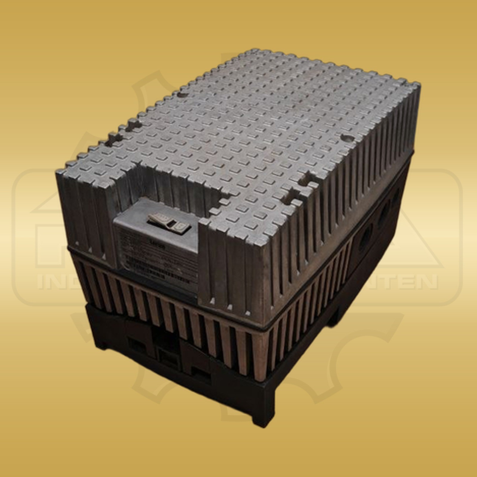
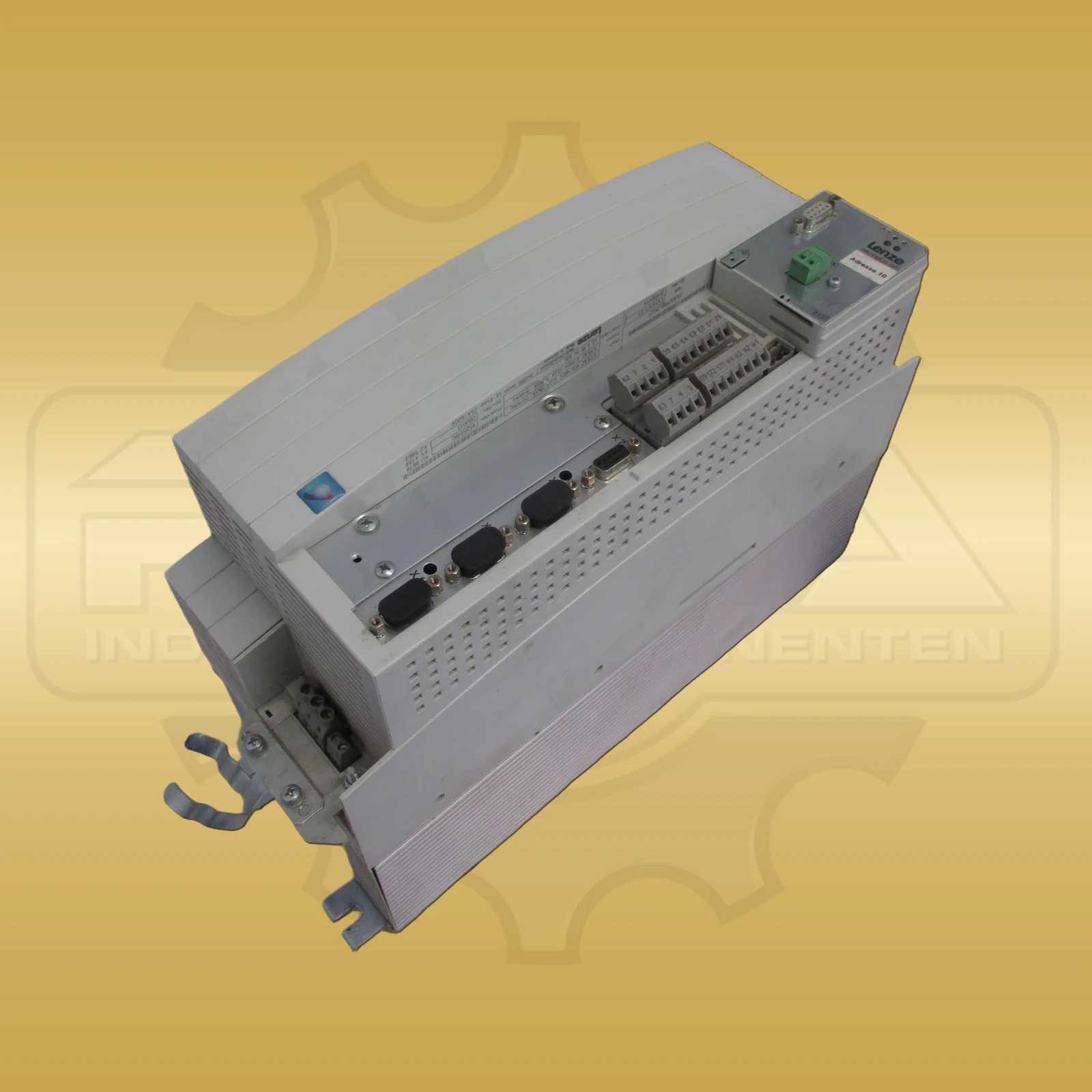
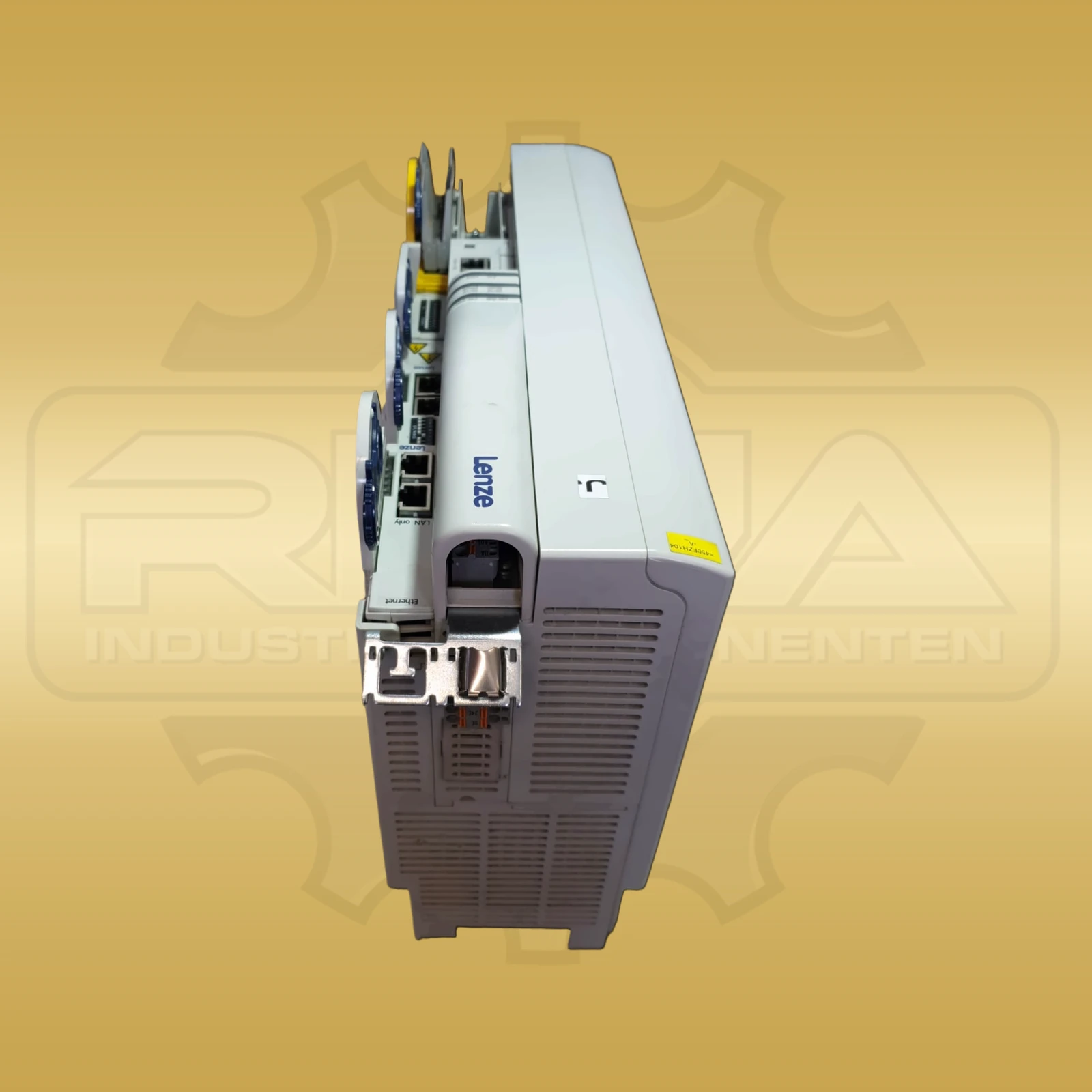
The Lenze 8400 motec is a decentralized frequency converter for motor-mounted or wall-mounted applications. The series is particularly relevant in conveyor systems, lifting technology and intralogistics systems.

This page is aimed at service technicians and maintenance personnel who need to diagnose a 8400 motec, assign a suitable replacement device or identify typical error patterns on connectors, hybrid cables and IP65-Anbindungen more quickly.

Series and product groups

How the Lenze error-code database is structured

The error-code search above is the main feature of this page. It displays the relevant information directly in each result without requiring additional subpages.

The tables further down show typical and frequently searched messages for technical orientation. Use the search field above to query the complete dataset.

Important: The tables below are representative excerpts for each product group. Use the error-code search above for the complete database.

Classification of the Lenze 8400 motec in practice

The Lenze 8400 motec is a decentralized frequency converter for motor-mounted or wall-mounted applications. In practice, the series is often used in conveyor systems, lifting technology and intralogistics systems where robust, compact and field-based drive solutions are required.

When troubleshooting, it is important that with the 8400 motec not only electrical parameters, but also connectors, hybrid cables, moisture, vibration load and the quality of the IP65-Anbindung play an important role. In practice, many faults do not arise directly in the power section, but rather at transitions and in the area of ​​decentralized assembly.

If you are looking for Lenze 8400 motec error codes, Lenze 8400 motec technical data or Lenze 8400 motec connection assignment, you will find the most important information here in a structured technical overview.

Core technical data

For the first classification, the 8400 motec is particularly relevant for the power range, protection type, type of installation, connection concept and control method. Especially with decentralized systems, this overview helps to correctly assign the device and narrow down typical sources of errors more quickly.

ParametersValue
Performance range0,25–7,5 kW
Rated voltage3 × 380–480 V AC ±10 %, 50/60 Hz
Protection classIP65 (standard version)
Rules procedureU/f characteristic curve, vector control (VFCplus / SLVC)
Ambient temperature0–40 °C
AssemblyDirectly on the motor or wall-mounted (decentralized topology)
ConnectionConnector, hybrid cable (power + control)
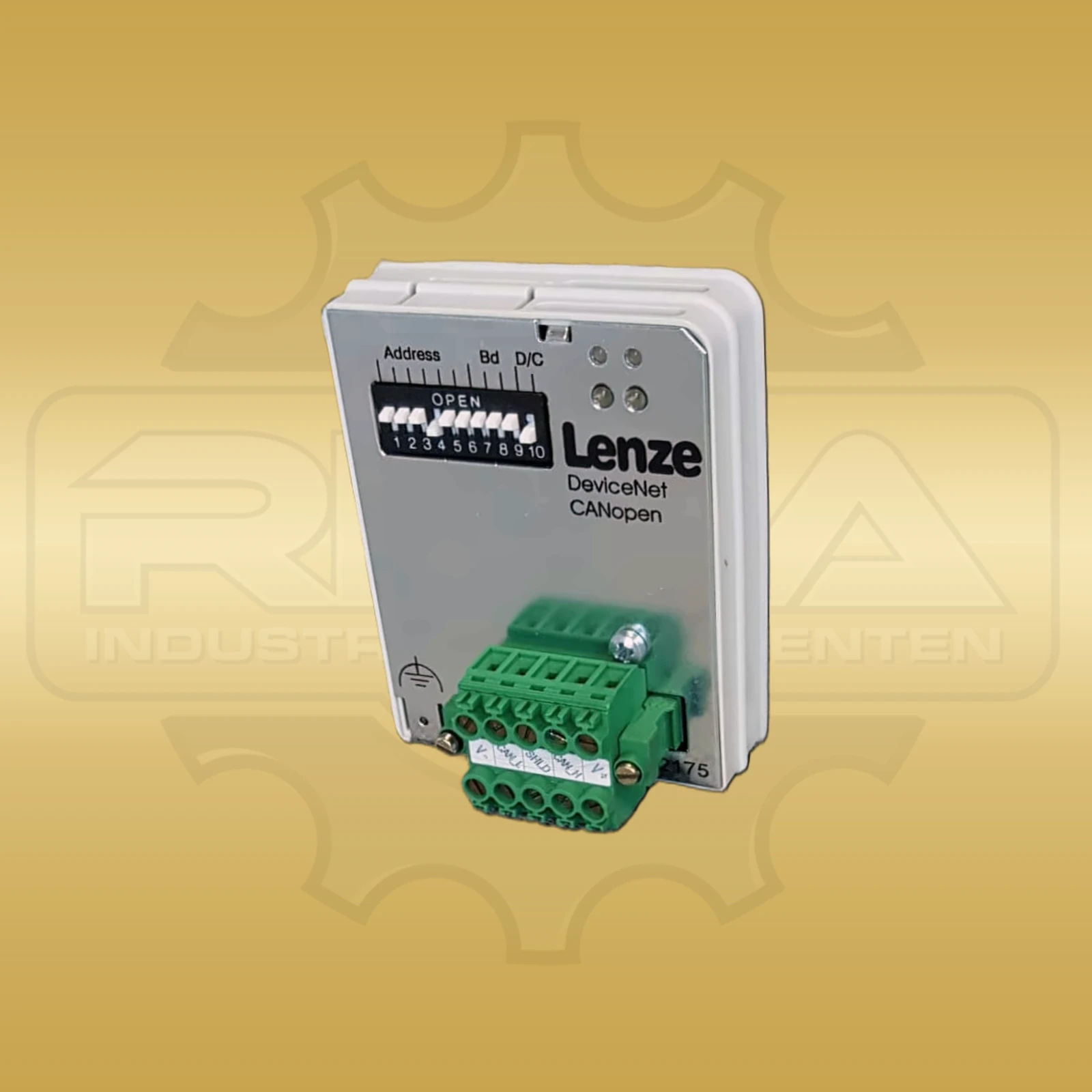
CommunicationAS-Interface or CANopen via separate plug-in modules

Model overview and order number system

The order number of the 8400 motec follows the pattern E84DGV + design + performance code + voltage code. In practice, this system is particularly important when a device has to be identified based on the nameplate or an existing article number.

The following overview refers to models for 3 × 400 V. This means that the appropriate performance class can be quickly assigned to the correct order number.

Order numberRated power
E84DGVB37242PS0,37 kW
E84DGVB55242PS0,55 kW
E84DGVB75242PS0,75 kW
E84DGVB11342PS1,1 kW
E84DGVB15342PS1,5 kW
E84DGVB22342PS2,2 kW
E84DGVB30342PS3,0 kW
E84DGVB40342PS4,0 kW
E84DGVB55342PS5,5 kW
E84DGVB75342PS7,5 kW

Pin assignment – connector X1/X2/X3/X4

Unlike classic frequency inverters with a terminal block, the 8400 motec works with plug connectors. In practice, it is precisely this design that is often a decisive factor in malfunctions when plug connections are not seated neatly or environmental influences such as moisture and vibrations play a role.

PlugDesignationFunction/Note
X1Mains connectionL1, L2, L3, PE – hybrid plug (power + control in one cable)
X2Motor connectionU, V, W, PE – three-phase motor connection
X3Control signalsController enable, setpoint (analog), digital inputs, status output
X4Brake connectionOptional – connection of external braking resistor
X106Engine temperatureT1/T2 – PTC/KTY-Engine temperature monitoring

Error codes and fault diagnosis

The following table lists the documented error messages of the 8400 motec. The display appears on the display or via the diagnostic parameter. Messages of the Fault type usually require manual acknowledgment, while Warnings can disappear automatically after the cause has been eliminated.

Note: Tip: The error memory can be accessed via the diagnostic parameter C00168. When installing decentrally in the IP65 version, you should always check whether all connectors are correctly seated and tight. Moisture and vibrations are among the most common causes of problems in practice.
CodeDescriptionCauseRemedy
An01AIN1_I < 4 mAWire break monitoring for analog input 1 has triggered. Only when configured as a 4...20 mA current loop.Check the wiring of the analog input X3/A1I for a wire break. Check minimum current values ​​of the signal sources.
CA06CAN CRC ErrorCAN onboard: An incorrect CAN-telegram was detected.Check wiring and bus terminating resistance. EMV-Eliminate malfunctions.
CA07CAN Bus warningCAN onboard: More than 96 incorrect CAN- telegrams sent or received.Check wiring and bus terminating resistance. Same baud rate. Different IDs. EMV-Eliminate malfunctions.
CA08CAN Bus stoppedCAN onboard: Device has received Stop Remote Node NMT-telegram.CAN-Check master.
CA0FCAN control wordBit 14 SetFail in the control word was set.Trace signal source on the CAN-bus that sets bit 14.
CA0bCAN HeartBeatEventHeartbeat telegram not received within the defined time.Reactivate the heartbeat producer by restarting or CAN reset node. Adjust heartbeat time.
CE1CAN RPDO1Time monitoring for RPDO1 has triggered.Set the correct telegram length. EMV-Eliminate malfunctions. Adjust monitoring time.
CE2CAN RPDO2Time monitoring for RPDO2 has triggered.Set the correct telegram length. Adjust monitoring time.
CE3CAN RPDO3Time monitoring for RPDO3 has triggered.Set the correct telegram length. Adjust monitoring time.
CE4CAN Bus offToo many incorrect telegrams, damaged cable or duplicate ID.Check wiring and bus terminating resistance. Same baud rate. Assign different IDs. EMV-Eliminate malfunctions.
CP04CAN RPDO4Time monitoring for RPDO4 has triggered.Set the correct telegram length. Adjust monitoring time.
FC01Switching frequency reductionLoad-dependent switching frequency reduction.Comply with load requirements. Correct dimensioning or reduce dynamics.
FC02Maximum speed for FchopMaximum speed for chopper frequency reached.Select maximum speed depending on the switching frequency.
FC03Limit field controllerOutput of the field controller has reached the maximum limit.Comply with load requirements. Correct dimensioning or target value.
Id1Motor data identification errorError during engine parameter identification.Check motor connections. Correct start parameters. Ensure power supply.
Id3CINH Engine data identificationController inhibit during motor data identification.Do not set a controller lock during motor data identification.
Id4Resistor identification errorCable cross-section or cable length implausible.Enter sensible values for the cable cross-section and cable length.
LP1Motor phase failureOne motor phase carries less current than set.Check motor connections and plugs. Check trigger threshold.
OC1Power section short circuitMotor phase short circuit detected. Often faulty motor connections.Check motor connections and plugs. Only use permitted combinations of device power and motor power.
OC10Maximum current reachedMaximum current has been reached.Check load dimensioning. Check maximum current settings.
OC11Clamp operation activeOvercurrent limiting clamp activated.Reduce the dynamics of setpoint generation or motor load.
OC12I2xt Brake resistor overloadBraking processes that are too frequent and too long.Check drive design.
OC13Exceeding maximum current for FchMotor current exceeds maximum current limit at fixed switching frequency.Pay attention to the maximum current setting and switching frequency. Reduce load or use dynamic switching frequency.
OC14Limitation of series current controllerLimitation of the series current controller active.Comply with load requirements. Correct dimensioning or dynamics.
OC15Limitation of cross-current controllerLimitation of the cross current controller active.Comply with load requirements. Correct dimensioning or dynamics. Check current controller parameters.
OC16Torque controller limitationActuator limitation according to speed controller.Comply with load requirements. Correct dimensioning or dynamics.
OC17Clamp sets pulse lockBrief overcurrent with brief inverter shutdown.Check load dimensioning. Reduce the dynamics of setpoint generation.
OC2Power section ground faultGround fault detected on a motor phase.Check motor connections and plugs. Use recommended motor filters, cable lengths and cable types.
OC5Ixt overloadIxt overload check triggered.Check the dimensioning of the device and motor load. Reduce load cycles.
OC6I2xt Motor overloadMotor thermal overload.Comply with load requirements. Correct sizing. Check Vmin Boost at VFCplus.
OC7Motor overcurrentInstantaneous value of the motor current has exceeded the limit.Check load dimensioning and correct if necessary.
OH1Overtemperature heat sinkHeat sink temperature is greater than limit temperature.Check ambient temperature. Clean filters and regulators. Ensure adequate cooling.
OH3Motor temperature X106 triggeredMotor temperature monitoring on X106 has triggered.Check engine temperature monitoring. Ensure engine cooling. Check lines.
OH4Heatsink temp. > Switch-off temp. -5°CHeatsink temperature is approaching shutdown temperature.Prevent further warming. Reduce motor load or set controller lockout.
OS1Maximum speed limit reachedMaximum speed limit reached.Limit setpoint specification to maximum values. Adjust speed and frequency limitation.
OS2Max. engine speedMaximum permissible engine speed reached.Limit the setpoint specification to the maximum permissible engine speed. Adjust max. engine speed.
OT1Maximum torque reachedMaximum possible torque reached on the motor shaft.Reduce engine load.
OT2Speed controller output limitedOutput of the speed controller has reached the internal limit.Comply with load requirements. Correct dimensioning or reduce dynamics.
PS01No memory moduleMemory module not present or not properly engaged.Insert memory module. Check correct fit.
PS02Par.set invalidParameter set in the memory module is invalid or incompletely saved.Ensure power supply during saving process.
PS03Par.set device invalidParameter set in the memory module incompatible with the basic device.Please note downward compatibility when replacing modules.
PS04Par.set MCI invalidMCI-Parameter set incompatible with the communication module.Please note downward compatibility when replacing modules.
PS07Par. memory module invalidMemory module parameters invalid.Check or replace memory module.
PS08Par.set device invalidDevice parameters invalid.Check device parameters.
PS09Par. format invalidParameter format invalid.Check parameter format.
PS10Memory module binding invalidMemory module binding invalid.Check memory module binding.
Sd3Wire break feedback systemHTL-Encoder cable interrupted or HTL-Encoder defective.HTL-Check encoder cable, encoder and terminals. Deactivate monitoring if encoder is not used.
Su02A network phase is missingWith a three-phase supply, one mains phase has failed.Check mains connection.
Su03Switching on the mains too frequentlyThe power unit was switched on and off too frequently.Acknowledge error by switching mains. Observe cooling times.
Su04CU inadequately supplied24-V-Versorgung of the control electronics too low.Acknowledge supply and check voltage stability.
Su06Mains input overloadOvertemperature in the input rectifier or the mains choke.Check whether all mains phases are connected. Ensure adequate cooling.
US01User error 1Custom error.Application dependent.
US02User error 2Custom error.Application dependent.
US03User error 3Custom error.Application dependent.
US04User error 4Custom error.Application dependent.
US05User error 5Custom error.Application dependent.
US06User error 6Custom error.Application dependent.
US07User error 7Custom error.Application dependent.
US08User error 8Custom error.Application dependent.
dF10AutoTrip ResetToo frequent auto-trip reset.Troubleshoot common errors.
dF14SW-HW invalidSoftware or hardware incompatibility.Check device and software status.
dF18BU RCOM errorBasic unit RCOM error.Power switching or restart.
dF21BU WatchdogBasic unit watchdog.Power switching or restart.
dF22CU WatchdogWatchdog control unit.Power switching or restart.
dF25CU RCOM errorControl unit RCOM error.Power switching or restart.
dF26Appl. WatchdogApplication watchdog.Check application.
dF50Retain errorRetain memory error.Mains switching.
dF51CuCcr errorCU-CCR Error.Mains switching.
dF52BuCcr errorBU-CCR Error.Mains switching.
dH09EEPROM power sectionEEPROM of the power section incorrect.Replace device.
dH10Fan failureFan failure detected.Clean or replace fans.
dH68Synchronization data error CUCalibration data from the control unit is incorrect.Replace device.
dH69Synchronization data error BUBasic unit calibration data incorrect.Replace device.

Spare parts and typical wear issues

Typical wearing parts for the 8400 motec are connector seals for the IP65-Schutz, fans for larger sizes, memory modules and intermediate circuit capacitors. Regular visual inspection of the connectors and seals makes sense, especially for decentrally mounted devices in harsh environments.

Before replacing a device, the parameter set should be saved via the memory module. This makes the commissioning of a replacement device significantly easier and reduces downtime.

Shop & Inquiry

Lenze 8400 motec devices and spare parts

After the technical classification, the direct route to the right replacement device, compatible spare parts or a specific product inquiry is usually the most sensible next step.

FAQ for Lenze 8400 motec

Which errors occur particularly frequently with the Lenze 8400 motec?

CAN-Communication errors, overcurrent messages, temperature errors and supply problems are common. Because of the decentralized IP65-Montage, plug connectors, seals and hybrid cables should also be checked particularly carefully.

What is the 8400 motec typically used for?

The 8400 motec is often used in conveyor systems, lifting technology and intralogistics. Its decentralized design is interesting wherever drives need to be installed close to the motor.

Which connections are particularly important when troubleshooting?

Particularly relevant are the mains connection X1, the motor connection X2, the control signals on X3 and the motor temperature monitoring on X106. In many cases it is also worth checking that all connectors are secure and tight.

How can the correct 8400 motec be identified based on the order number?

The order number contains information on the design, performance code and voltage code. This allows the device to be assigned to a specific performance class within the 8400-motec-Baureihe.

Disclaimer and safety notice

The information on this page has been compiled with the greatest care and is based on many years of practical experience with Lenze frequency converters. However, they do not replace the official Lenze documentation and serve exclusively as a guide for qualified specialist personnel.

Work on frequency converters may only be carried out by qualified electricians in accordance with DIN VDE 0105-100. Danger to life due to residual voltage in the DC link: After switching off, wait at least 10 minutes or adhere to the waiting time specified by the manufacturer.

REHA-Industrial components assumes no liability for damages resulting from the use of this information. Lenze is a registered trademark of Lenze SE.